Introduction to optics
Section titled “Introduction to optics”Visible light is an electromagnetic wave with wavelength . This notes pages will separate optics into two parts: geometric optics and wave optics. Whether to treat it as rays or as waves depends on the size of the features it interacts with:
Reflection
Section titled “Reflection”Theorem (Law of Reflection). At a smooth surface, the angle of incidence equals the angle of reflection, both measured from the normal, and the incident ray, reflected ray, and normal are coplanar:
A plane mirror forms a virtual, upright image the same size as the object, located as far behind the mirror as the object is in front. The image is reversed front-to-back (which is why text appears mirror-flipped). Think of it like staring into your standard bathroom mirror.
Example. How tall must a vertical plane mirror be for you to see your whole body, and does the answer depend on how far you stand from it?
Let your eyes be at height and the top of your head at , feet at the floor (). To see the top of your head, a ray must leave the head, reflect off the mirror, and reach your eye. By the law of reflection the reflection point lies exactly halfway in height between the head and the eye, at height . To see your feet, the ray reflects at height (halfway between eye and floor). The mirror therefore only needs to span from to , a length
where is your full height. The required length is half your height, and notice the horizontal distance to the mirror canceled completely — the reflection-point heights depend only on the heights of head, eye, and feet, not on how far away the mirror is. The mirror’s position (it must be hung with its bottom edge at ) is what matters, not its distance.
Refraction and Snell’s law
Section titled “Refraction and Snell’s law”Refraction is the phenomena where light bends when entering a different medium (substance).
Definition (Index of refraction). The index of refraction of a medium is defined as
the ratio of the speed of light in vacuum to its speed in the medium ().
Crossing a boundary, the ray bends according to Snell’s law:
Theorem (Snell’s law). At a boundary between media of indices and ,
Going into a denser medium (larger ), the ray bends toward the normal. Across the boundary the *requency stays fixed (it is set by the source), so the wavelength must change:
Example. A coin lies at depth at the bottom of a pool of water (index ). Looking straight down, how deep does it appear?
A ray leaves the coin at a small angle to the vertical inside the water and refracts to angle in air, with . Trace two such rays back: to the eye they appear to diverge from a shallower point at apparent depth . If the rays emerge at horizontal distance from the point above the coin, then and , so
For near-normal viewing all angles are small, so , and Snell gives . Hence
A pool of true depth () looks only deep — which is why pools always seem shallower than they are. (Viewed at a steep angle the apparent depth shrinks further, since and diverge.)
Total internal reflection
Section titled “Total internal reflection”When light travels from a denser to a less dense medium (), Snell’s law has no solution once would exceed .
Definition (Critical angle). Define the critical angle as the angle where all the light is reflected back instead of refracting (total internal reflection (TIR)). The angle is given by:
This is how optical fibers trap light and why a diamond (, so ) sparkles. For a water–air boundary ; for a typical glass () it is , which is why a glass prism makes a perfect internal mirror in binoculars.
Thin lenses and ray tracing
Section titled “Thin lenses and ray tracing”A thin lens has thickness small enough to neglect compared with the relevant distances. In the paraxial approximation, it obeys the thin-lens equation and magnification relation:
and are the heights of the image and the object, respectively. Note that a negative height/magnitude means the image is inverted.
Proof (Thin lens equation). Consider a converging thin lens at , a real upright object of height at , and a real image of signed height at . Work with paraxial rays, close to the axis, and the same medium on both sides.
A ray through the optical center travels straight in the thin-lens approximation. Similar triangles on either side give
A second ray leaves the object parallel to the axis at height . It refracts through the far focal point . Its outgoing slope is , so at the image plane,
Equate the two expressions for the height ratio:
The construction used a real image, but signed distances extend the formula to virtual objects and images. For a real object on the incoming side, ; a real image on the outgoing side has , and a virtual image on the incoming side has . Converging lenses have and diverging lenses have .
The lensmaker’s equation
Section titled “The lensmaker’s equation”Theorem (Lensmaker’s equation). A thin lens with refractive index surrounded on both sides by the same medium of index has focal length
Take light to travel left to right. is the signed radius of the first surface and of the second. A radius is positive when that surface’s center of curvature lies to its right, and negative when it lies to its left. A plane surface has and contributes zero.
For a biconvex glass lens in air, and , so . For a biconcave lens, and , giving . In air, use . The formula assumes spherical surfaces, negligible thickness, and small ray angles.
A thin lens is just two spherical surfaces back-to-back. Applying the single-surface formula twice and adding gives the lensmaker’s equation as a clean proof.
Proof (Lensmaker’s equation). A thin lens of index sits in air (), with front surface radius and back surface . Surface 1 (air glass) images the object at to an intermediate image at :
This intermediate image acts as the object for surface 2 (glass air). For a thin lens the two surfaces coincide, so the object distance for surface 2 is (a real image behind surface 1 is a virtual object for surface 2). Thus
Add the two equations; the terms cancel:
Comparing to the thin-lens form identifies the focal length:
Types of thin lenses
Section titled “Types of thin lenses”The words convex and concave describe the shape; converging and diverging describe what the lens does to parallel rays in its surrounding medium.
| Lens shape | Cross-section idea | In air | Sign of | Ray behavior |
|---|---|---|---|---|
| Biconvex | thickest in the middle | converging | parallel rays meet at the far focal point | |
| Plano-convex | one flat side, one convex side | converging | common simple positive lens | |
| Positive meniscus | one convex and one concave side, thicker in middle | converging | weaker/aberration-controlled positive lens | |
| Biconcave | thinnest in the middle | diverging | parallel rays spread as if from the near focal point | |
| Plano-concave | one flat side, one concave side | diverging | common simple negative lens | |
| Negative meniscus | one convex and one concave side, thinner in middle | diverging | weaker/aberration-controlled negative lens |
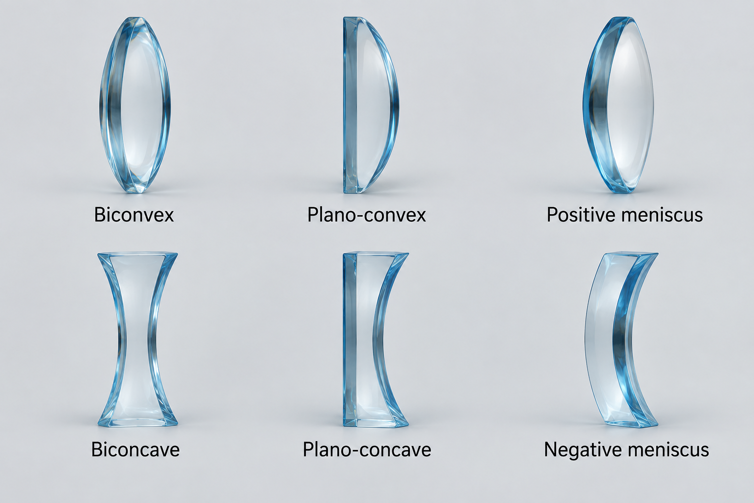
Generated photographic illustration of the six lens shapes. The table describes their behavior when the lens index exceeds the surrounding medium’s index.
In ordinary air, a lens thicker in the middle is usually converging and a lens thinner in the middle is usually diverging. If the surrounding medium has a higher index than the lens, the behavior can reverse, because the lensmaker’s equation depends on the index contrast, not just the visual shape.
Principal rays for lenses
Section titled “Principal rays for lenses”For ray tracing, we assume that light emits from an object as rays in every direction. However, to determine the position of the image, we only need to draw the three principal rays from the top of the object. When the outgoing rays meet, it forms the image. If the outgoing rays diverge, extend them backward with dashed lines; where the extensions meet is a virtual image (it would have existed there in the eyes of an observer).
For a converging (biconvex) lens:
- A ray parallel to the axis refracts through the far focal point.
- A ray through the near focal point emerges parallel to the axis.
- A ray through the center of a thin lens continues nearly straight.
For a diverging (biconcave) lens:
- A ray parallel to the axis refracts outward as if it came from the near focal point.
- A ray aimed toward the far focal point emerges parallel to the axis.
- A ray through the center of a thin lens continues nearly straight.
Image cases
Section titled “Image cases”For a converging lens:
- : real, inverted, reduced image between and .
- : real, inverted, same-size image at .
- : real, inverted, enlarged image beyond .
- : outgoing rays are parallel, so the image is at infinity.
- : virtual, upright, enlarged image on the object side.
For a diverging lens with a real object, the image is always virtual, upright, reduced, and on the object side.
Example. An object sits in front of a converging lens of focal length . Use ray tracing first, then calculate the image location and magnification.
Since , the ray diagram should give a real, inverted, reduced image between and on the far side. Now use the thin-lens equation:
Since , the image is real and on the far side of the lens. The magnification is
so the image is inverted and half the object’s size — exactly the behavior of a camera or a projected slide.
For a system of lenses, work through them one at a time: the image of the first lens becomes the object of the second (a real image on the incoming side of the next lens counts as a positive object distance; an image that would form behind it is a virtual object with negative distance). The total magnification is the product, .
Fermat’s principle
Section titled “Fermat’s principle”Theorem (Fermat’s principle). Light travels between two points along the path that takes a stationary (usually minimum) time. This is why light sometimes won’t take a straight path from one point to another.
Proof (Snell’s Law, using Fermat’s principle). Light goes from point in medium to point in medium , crossing the boundary at horizontal position . If is height above the boundary at horizontal , and is depth below at horizontal , the travel time is
This can be derived from Pythagorean theorem and basic kinematics. Setting ,
The two fractions are equal to and , so
using . The law of reflection follows from the same principle with both points in one medium.
Dispersion
Section titled “Dispersion”The index of refraction actually depends slightly on wavelength, , with blue light (short ) refracting more than red in most glass. This dispersion is why a prism spreads white light into a spectrum and why rainbows form (refraction + internal reflection + dispersion in water droplets).
Gradient-index refraction and mirages
Section titled “Gradient-index refraction and mirages”When the index varies continuously rather than in a sharp jump, Snell’s law still applies across each infinitesimal layer, and the quantity (angle from the vertical) is conserved along the ray. The ray curves smoothly, always bending toward the region of higher : toward slower light. Applying Snell’s law to two nearby heights, a ray climbing through an index gradient turns through an angle per unit horizontal distance.
This is the physics of mirages. In the atmosphere , so a temperature gradient bends light:
- Over hot ground (desert road), the air is hottest at the bottom, so increases with height and rays bend upward. You see an inverted image of the sky on the ground — the shimmering “water” of an inferior mirage.
- In a thermal inversion (cold air below warm, e.g. over cold water), decreases with height, rays bend down to follow the Earth’s curvature, and distant objects appear lifted above the horizon — a superior mirage.
If the downward bending is strong enough to match the Earth’s curvature, , light rays literally orbit at constant height and you can see beyond the geometric horizon.
Refraction at a spherical surface
Section titled “Refraction at a spherical surface”Before lenses, consider a single spherical refracting surface of radius separating media (object side) and . This is the building block for the lensmaker’s equation. We use the real-is-positive convention: object distance for a real object in front, image distance for a real image on the far side, and when the center of curvature is on the far (outgoing) side.
Proof (Single-surface refraction). Take a point object on the axis at distance in front of a surface with center of curvature at distance behind the vertex. A paraxial ray leaves , hits the surface at height , and refracts toward the image at distance . Let be the (small) angles the object ray, image ray, and surface normal (the radius) make with the axis, so
The angle of incidence (from the normal) is and the refraction angle is (exterior-angle geometry of the small triangles). Paraxial Snell, , gives
Substitute the angle expressions and divide by :
Example. A fish sits a distance from the near wall of a large spherical fishbowl of radius (water , air , glass thin enough to ignore). Where does the fish appear to an outside observer?
Light goes water air, so , . The surface bulges toward the observer (outgoing side), and the center of curvature lies on the object (water) side, so by our convention . With ,
So , giving . The negative sign means a virtual image on the object side: the fish appears about behind the glass (closer than its true ), slightly magnified — which is why fish in round bowls look closer and bigger than they are.
Spherical mirrors
Section titled “Spherical mirrors”A spherical mirror of radius has focal length
Object and image distances obey the thin lens equation (as described above).
Sign conventions (real-is-positive):
- for a real object in front of the mirror.
- for a real image (same side as object, in front); for a virtual image (behind).
- for a concave (converging) mirror; for convex (diverging).
- upright, inverted; enlarged.
The reason a curved mirror focuses at all comes out cleanly for conic-section shapes, which have exact reflection properties:
- An ellipse reflects every ray from one focus to the other focus.
- A parabola reflects all rays parallel to its axis to a single focus (and vice versa) — the principle behind satellite dishes, headlights, and reflecting telescopes. A parabola is just an ellipse with its second focus sent to infinity, which is why parallel rays (a source at infinity) come to a point.
- A hyperbola reflects rays aimed at one focus so they diverge as if from the other.
A spherical mirror only approximates a parabola near its axis; rays striking far from the axis miss the focus, an error called spherical aberration.
Prisms and minimum deviation
Section titled “Prisms and minimum deviation”A ray passing through a prism of apex angle is bent through a total deviation — the angle between the incoming and outgoing rays. Refraction at each face turns the ray, and the geometry of the two faces gives
where are the external angles at the two faces and the internal angles. (The relation comes from the triangle formed by the two normals and the apex.)
Proof (Minimum deviation). As varies, has a minimum. At the minimum, . Since ,
Differentiating Snell at each face (, ) and the constraint (so ), one finds this is satisfied only for the symmetric ray:
Then , so , and Snell at the first face gives
This symmetric, minimum-deviation configuration is how prism spectrometers measure precisely: rotate the prism until the deviated image stops moving and reverses.
For a thin prism ( small), all angles are small, so and the formula linearizes to , giving
The rainbow
Section titled “The rainbow”A rainbow is sunlight refracting into a spherical raindrop, reflecting once off the back, and refracting out. The classic olympiad calculation finds the angle at which this light piles up.
Proof (Primary rainbow angle). A ray enters the drop at incidence angle , refracting to with . It bends by at entry, reflects off the back turning by , and bends by again on exit. The total deviation is
Light scattered by the drop bunches up at the angle where is stationary (rays near it all emerge in nearly the same direction — a caustic), so set :
Differentiate Snell, , so . Square and use :
For water : , so , , . Then
The rainbow is seen at from the antisolar point — the familiar primary bow.
Because is larger for blue light, blue deviates more (smaller rainbow angle), so red is on the outside, violet on the inside of the primary bow. The secondary bow comes from rays that reflect twice inside the drop, with deviation ; minimizing gives a bow at with reversed color order (red inside). Between the two bows, –, very little light emerges from any drop — the noticeably darker band of sky known as Alexander’s dark band.
Ray transfer (ABCD) matrices
Section titled “Ray transfer (ABCD) matrices”For paraxial rays, a ray at a plane is described by its height and slope (small angle). Each optical element acts as a matrix on the vector , and a whole system is the product of the element matrices (applied right-to-left, in the order light meets them).
- Free propagation a distance : , slope unchanged:
- Thin lens of focal length : height unchanged, slope bent by :
- Refraction at a curved surface (radius , ):
For a system matrix , the imaging condition (all rays from an object point reconverge regardless of slope) is , and then is the magnification. The element gives the system focal length via .
For two thin lenses separated by distance , the matrix product gives the useful effective-focal-length result
Setting gives the contact-lens rule .
Optical instruments
Section titled “Optical instruments”The eye’s relaxed near point is ; angular magnification compares the angle an object subtends through the instrument to the angle it would subtend held at .
- Simple magnifier (object at the focal point, image at infinity): .
- Refracting telescope (objective , eyepiece , in afocal configuration): (the minus sign = inverted image).
- Compound microscope (objective forms a real image at tube length , eyepiece magnifies it): .
Huygens’ principle
Section titled “Huygens’ principle”Wave optics rests on Huygens’ principle: every point on a wavefront acts as a source of secondary spherical wavelets, and the new wavefront is their envelope a moment later. This reproduces straight-line propagation, reflection, and refraction, and — crucially — explains why waves bend (diffract) around edges and through gaps.
Coherence. Interference fringes only appear if the two combining waves keep a stable phase relationship; such waves are called coherent. This is hard with ordinary light: even a single-frequency lamp’s phase wobbles randomly on nanosecond timescales, and two separate lamps never stay in step, so their interference term averages to zero and you see no fringes. The 19th-century fix was to illuminate the experiment through a tiny pinhole, so that the light reaching both slits originates from the same point and is automatically in phase with itself — good enough that even sunlight works. Lasers make this trivial today, since they emit highly coherent light. For the idealized problems below we assume perfect coherence, but in any real setup it is the first thing to check.
Interference: Young’s double slit
Section titled “Interference: Young’s double slit”Two coherent sources (or one wavefront split by two slits a distance apart) produce alternating bright and dark fringes on a distant screen. For a screen far away, the path difference to a point at angle is , giving
for integer . For small angles on a screen a distance away, the fringes are evenly spaced by
Example. Light of wavelength falls on two slits apart, and the pattern is viewed on a screen away. How far apart are adjacent bright fringes?
Solution. The fringe spacing is
Measuring this spacing is a standard way to determine an unknown wavelength.
When mirrors or lenses are in the way, computing path-length differences directly is a nightmare. The shortcut is that any image — real or virtual — can be treated as its own coherent point source, so you measure path differences starting from the images rather than tracing all the way back to the original object. (For a real image this follows from Fermat’s principle: every ray from object to image takes the same time, so they all arrive in phase and leave the image in phase.) Setups like Lloyd’s mirror or two slightly tilted mirrors reduce to an ordinary double slit whose two “slits” are the image sources — even though there is only one real light source. A useful caution: reflection adds a phase of , though it often cancels out when both images reflect the same way.
The Michelson interferometer
Section titled “The Michelson interferometer”A beamsplitter sends light down two perpendicular arms to mirrors and recombines them. Moving one mirror by changes that arm’s round-trip path by , sweeping the central fringe through bright–dark cycles:
Each fringe that passes corresponds to a half-wavelength of mirror motion, so counting fringes measures very small displacements.
Inserting a gas cell of length and changing its index by shifts the fringe count by
because the light passes through the cell twice.
Thin films
Section titled “Thin films”Light reflecting off the top and bottom of a thin film of thickness and index interferes. Two subtleties decide the condition:
- The path difference inside the film is (using the wavelength in the film).
- A reflection off a higher-index medium flips the phase by (half a wavelength); off a lower-index medium it does not.
For a film with a higher index than its surroundings on both sides (e.g. a soap film in air), only the top reflection flips, giving a net half-wavelength shift, so
If instead there is a phase flip at both surfaces (or neither), the conditions swap. Always count the -shifts first — this is the most common place to go wrong.
Example. A camera lens () is coated with magnesium fluoride () to suppress reflection at (green). Find the minimum coating thickness, and state the index that would give zero reflection.
Light reflects off aircoating (, flip) and coatingglass (, also a flip). Both flip, so the flips cancel and destructive interference of the reflections requires the round-trip path to be a half-integer number of in-film wavelengths:
The minimum is :
This is the standard quarter-wave coating, . For the two reflected amplitudes to be equal (and thus cancel completely), the coating index should be the geometric mean of its neighbors:
MgF at is the closest cheap, durable material — hence the faint purple sheen on coated lenses.
For Newton’s rings, where a plano-convex lens sits on a flat plate and makes a thin air gap, the reflected pattern has a dark center and dark-ring radii
where is the lens radius of curvature. This comes from and one reflection phase flip.
Diffraction
Section titled “Diffraction”A wave passing through a single slit of width spreads out, producing a broad central maximum flanked by weaker side maxima. The minima occur at
(note: this is the condition for dark fringes, the opposite of the double-slit bright condition). The central maximum is twice as wide as the others, with angular half-width — narrower slits diffract more.
Example. A slit of width is lit by (He–Ne laser); the pattern falls on a screen away. How wide is the central bright band?
The first minima sit at , and for small angles . The central maximum spans from to , so its full width is
Note the central band is twice as wide as the side fringes (whose spacing is ), and it widens as the slit narrows — the hallmark of diffraction.
A diffraction grating with closely spaced slits of separation produces very sharp bright lines (principal maxima) wherever
Summing the equally spaced, equal-phase-step contributions as a geometric series gives the intensity
a set of tall, sharp principal maxima (where all slits are in phase, ) separated by faint secondary maxima. More slits make the principal maxima sharper and brighter, which is why gratings outperform double slits for measuring wavelengths and separating spectral lines.
The quality of a grating as a spectrometer is its resolving power — the ratio of a wavelength to the smallest wavelength difference it can split apart. Taking two lines to be just resolved when the maximum of one sits on the first minimum of the other (the Rayleigh criterion again) gives a strikingly simple result:
the number of slits times the diffraction order. To resolve finer spectral detail you either illuminate more lines or work at a higher order.
Resolution and the Rayleigh criterion
Section titled “Resolution and the Rayleigh criterion”Diffraction sets a fundamental limit on resolving two nearby point sources through an aperture of diameter . By the Rayleigh criterion, they are just resolvable when the center of one diffraction pattern falls on the first minimum of the other, at angular separation
Bigger apertures (telescope mirrors, eye pupils) and shorter wavelengths give finer resolution.
Babinet’s principle
Section titled “Babinet’s principle”Babinet’s principle states that an opaque obstacle and an aperture of the same shape produce identical diffraction patterns (away from the central beam). The argument is short: the aperture and the obstacle are complementary, so their amplitudes add up to the wave you’d get with no screen at all — a single bright forward spot and darkness elsewhere. At any point that would be dark, the two amplitudes must therefore be equal and opposite, hence equal in magnitude, so they give the same intensity.
The practical payoff is that you can analyze diffraction off a small object (a wire, a strand of fiber, a dust speck, a circular disk) by pretending it is a slit or hole of the same size. It is what lets a laser pointer aimed at a helical spring — or X-rays aimed at the double helix of DNA — reveal the structure’s spacing and pitch from the diffraction pattern alone.
Polarization
Section titled “Polarization”Because light is a transverse wave, the orientation of its electric field — its polarization — matters. An ideal polarizer transmits only the field component along its axis. Unpolarized light passing through a polarizer loses half its intensity and emerges polarized.
For light already polarized at angle to a polarizer’s axis, Malus’s law gives the transmitted intensity:
Example. Unpolarized light of intensity passes through three ideal polarizers with axes at , , and . Find the transmitted intensity, and explain the surprise that removing the middle one blocks all the light.
After the first polarizer, unpolarized light is halved and polarized at : . The second polarizer is at to that:
The third is at , i.e. from the second’s axis:
So gets through. The surprise: with only the and polarizers (crossed), and nothing passes. Inserting the polarizer in between re-projects the field onto an intermediate axis at each step, so neither projection is a full — light leaks through. A polarizer is not a passive filter that only removes; it actively rotates the polarization onto its own axis.
Light can also be polarized by reflection. At Brewster’s angle the reflected ray is completely polarized (parallel to the surface), and this happens exactly when the reflected and refracted rays are perpendicular:
For sunlight reflecting off water, from the normal. The reflected glare is polarized parallel to the surface, which is why vertically oriented polarized sunglasses reduce it.
Problem-solving strategy
Section titled “Problem-solving strategy”A quick decision tree for picking the right tool:
Common traps: